Let's Build A Synthesiser
Let's Build A Synthesiser youtube video
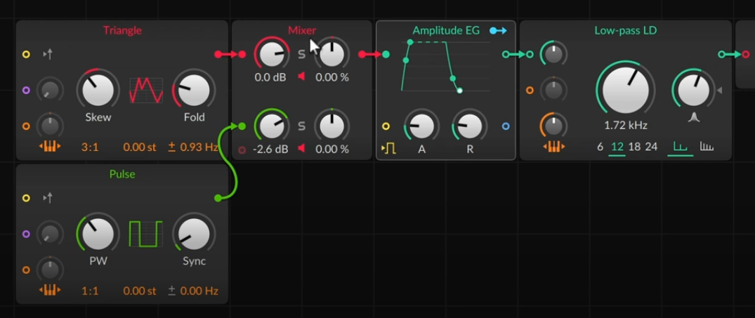
Let's build a synth with three sound sources.
- We begin with a single 'triangle' oscillator.
- To mix multipel sounds, we use a mixer.
- Add a pulse oscillator; route triangle to the first input on the mixer, pulse to the second input on the mixer.
- Set triangle pitch mult to 3:1 (lower left, to right of pitch mod) so itis an octave and fifth above the pulse.
- We could also use a frequency offset or semitone offset. This can cauase acoustic beating.
- To add stereo effect, the ± means that when the left pitch goes up, the right goes down.
- Add a ladder lowpass filter after the AR.
Current state of play:
- Add a second envelope to modulate the cutoff. Use an AR. Connect its output to the cutoff input (second down on left) of the lowpass filter.
- Let's add a third sound source. In this case, a noise. (Random section of palette. The empty circle in the mixer at the botton left is where we drag to make a new input.
- Let's give the noise its own envelope. So add an AD between the Noise and the Mixer.
- Add a waveshaper to the triangle: try Chebyshev.
- Modulator Sources: For something without an input, we can click the routing button
which allows us to modulate anything:

- There is a blend mixer which balances between two inputs (that is, fully anticlock is 100% 1 and 0% 2, through to fully clock is 0% 1 and 100% 2). We can then modulate this.
- This frees up a mixer channel, so let's fill it with something else. Let's use a sampler. Wire this to the middle channel in the mixer. Drag in an audio file. We use the Tolcha Clavint (which is a multisample -- bigwig multisamples are a zip with samples and an XML file detailing the mapping).
Modular Concepts - Phase - A Matter of Timing
Modular Concepts Phase youtube video
Three typical descriptors: pitch, timbre, loudness, often moving over time to make things interesting with a sense of motion.
If there was no motion, we still have all three. But it is more interesting when all these are moving. Timing of these is what we call phase.
Phase is a signal that goes linearly from 0 to 1 over a period. Phase counter then break this into steps, such as a Trigger with /8 producing 8 equally spaced triggers per period.
Now the step sequencer works without a Trigger explicitly, since it has a pre-cord to an implicit Trigger.
Other phase elements:
- Reverse: \(x\mapsto 1/x\).
- Phase shift: \(x\mapsto (x+c)\ (\mathrm{mod}\ 1)\)
- Phase reset: restart phase every time a trigger happens.
Example patch:
- Step sequencer drives filter cutoff. When patch is poly, we can see indications of where each voice is in the step sequencer.
- We can can use a Value instead of phase into a step sequencer. Interestingly, when the Value gets to 1, the step sequencer resets to 0, as \(1=0\ (\mathrm{mod}\ 1)\).
- We can use an LFO. By default this gives a unipolar value. We can use this to control the position in a step sequencer. A saw up unipolar LFO is basically a phase signal. But we can use different shapes.
- We could multiply the output of the LFO by velocity.
Let's Build a Sequencer
Let's Build a Sequencer youtube video
Most of the time an instrument takes in notes, and the notes determine the output. But we don't have to do this.
- Start with default patch.
- If we remove the AR envelope, we have a continuous tone coming out.
- We can generate sounds with a sequencer instead.
- We are interested in the Envelope and Data sections of the palette. Data has various sequencers.
- We can connect a Gates to a trigger input of an AD envelope. Gates has a pre-cord to a phase.
- We can use the original clock signal via Phase In, and connect that to the Gates's. Then we can process this signal. For example a Phase Scaler. Note that this shows that a phaser isn't really sending 0-1 signals. but a continuously increasing signal, and the \(mod\ 1\) is happening later.
- Click alt drag to duplicate and get a third element.
- We can create a hihat with Noise modulating a Sine going through an AD. We can make a closed hat with a short AD, and an open hat with a long AD. We can then use a clock divide to switch between the two.
- Let's add a fourth element by duplicating the previous. Colour them blue. This time we want to make the bass element. So make the Gates Scaler slower, bring the Sine pitch down (via ratio), Add some distortion after the AD.
- Let's add a Pitches sequencer. This goes into the pitch in on the Sine. Add a pattern to the Pitches. By default this Pitches has a phase pre-cord. Instead, we want it to step only when the Gates triggers, so route Gates out to a Counter going into the Pitches input.
Modular Concepts - Math
Any patch is using a lot of maths:
- Signals added
- Multiplication of level adjustments
- Selective kind, such as frequency dependent amplifier like a filter
- Ring modulation
- Amplitude modulation
- Logical function (e.g. when Gates triggers and when transport is playing)
Example 1
- Start with a Poly Grid. Set polyphony to 5.
- Let's make it velocity sensitive.
- We multiply the output of the AR by velocity.
- Range is too wide, so we look in Level category, select Level Scaler. This sets minimum and maximum and scales between these. \(x\mapsto a + (b-a)x\).
Example 2
- Start with Poly Grid.
- We have a square width. We want to put this through a lp filter. Using a scope, we see that the filter rounds off the abrupt changes in the input signal.
- What else can we do with the filter?
- We can put MIDI pitch through a lp, and this gives is a porta. The Lag module is specialised for this purpose.
Example 3
- Start with Poly Grid.
- We want to consider logical and and or.
- Use an AD envelope, which we want to loop.
- When AD reaches 0, we want to retrigger it, provided we are still holding the key down.
- Add a = comparitor, connect the AD env output to one input of the =
- Add an And with the = connected to one of its inputs.
- Add a Gate In and connect it to the other input of the And. Also connect it to the input of the AD.
- Connect the output of the And to the input of the AD.
- We have a feedback loop, so add a Long Delay with min delay time, send the output of the And into the Delay, and the output of the Delay into an Or. The Gate goes into the other input of the Or. And the output of the Or triggers teh AD.
- Finally¸ the AD only triggers at an zero to nonzero transition, so we want a Gate Length modifier on the nputs to the Or.
Let's Build a Distortion
Lets Build a Distortion youtube video
-
Note: clips in Bitwig can contain notes and devices.
-
We want an FX grid rather than Poly grid. The default patch has a simple patch cord from input to output.
-
Demo uses two displays: spectrum and wave.
-
Let's just add a Gain. This causes clipping, which squares off waveforms.
-
Audio Out has three clipping modes: Off, Hard, Soft. By default clipping is on.
-
Look at Leve category. We have a Clip module. This sets a threshold at which clipping occurs.
-
Distortion typically adds frequency content.
-
We can add a low pas filter afterwards. (For now bypassed.)
-
Shaper category:
- Distortion. Uses a sine-ish saturation curve.
- Bend. Concave: Quiet signals get quieter. Convex: Quiet signals get louder.
- Wavefolder. Very loud signals wwrap back around.
- Quantiser. Quantises values. One half of bitcrusher.
-
We can use these in combination. One is to split into bands.
- Take a 1 pole hp filter. Then subtract the hp output from the original to produce a low band. This is a two band crossover filter.
- We can apply one distortion to the low band, and another to the upper band. Then we add the outputs.
- Let's use the min/max module. There are two signal inputs, it compares the two, and puts the higher out of one side and the lower out of the other. With no second input, we are comparing to zero. Then the positive comes out of one side, and the negative out of the other.
- Then we can put one distortion on the negative portion, and another on the other.
-
Grid can listen to incoming notes.
- For example filters can key track.
- We could take the pitch from the IO palette. This can then go into a modulator module, and this can then modulate various controls.
Let's Build an Arpeggiator
Let's Build an Arpeggiator youtube video
An arpeggiator is a common note effect. It takes a set of held notes, and then outputs them one at a time.
- Start with a default Poly Grid.
- If we take the LFO and connect it to the pitch control of the Triangle, it modulates the pitch. If we use a square, it alternates between two pitches. With the attenuator fully open, input is treated as absolute pitch.
- Insert a Pitch Scaler between the LFO and the Triangle. Set range to be C3 to C4.
- We want to quantise the pitches. So insert a By Semitone. We can display the pitch control CV in an oscilloscope. We can use a single input add to recolour an input.
- Now we can use Pitch Quantise to quantise to a selection of pitches.
- The Pitch Quantise has two modes: Nearest and Uniform. Uniform spreads the input range equally between the selected pitches.
- Pitch Quantise has an optional pre-cord to use Note Input.
- The LFO is set to retrigger, so changes whenever we change notes. We can disable this.
- Currently this is monophonic. Let's switch the AR for an AD. This doesn't retrigger for each pitch change in the pitch quantise. So we want to detect changes in the output pitch from the Pitch Quantize.
- We try to use a ≠, and a delay so as to remember. But when we let go of the notes, things go crazy. So we only want to do this when notes are held down. So combine this with a Gate In module. We combine with an And.
- We could use this for other things.
- We could add a Dice to the output of the And. Then add a Level Scaler, and connect the output to a Multiply between the scaled Dice and the AD.
- Remember that every Grid signal is stereo. We could offset the left/right channels of the LFO. Then one output is delayed compared to the other.
- If we insert a LR Gain module between the LFO and Pitch scaler, We can change which notes occur in left and right.
Modular Concepts: Perspectives on Pitch
Modular Concepts Perspectives on Pitch youtube video
Pitch is the 'highness' or 'lowness' of sound. Pitch change can also be a timbre change.
- There are a multitude of ways to control pitch. Pitch input, vibrato, etc.
- Ratios allow one to sweep through the harmonic series. E.g. 4:1 puts an oscillator two octaves up.
- We can turn of key tracking.
- Sine has ratio, semitones and hz offsets. Using Hz gives a constant rate of beating. Stereo detune ± makes detune move left up and right down or vice versa. Remember that cords are stereo by nature.
- There is a stereo split module that outputs L R M S individually.
- The oscilloscope has a pitch mode by default whichis good for viewing oscillator waveforms.
- Filters often have key tracking. Bitwig Polysynth device has many key tracking options for its filters.
- In Bitwig, all note information is passed down the entire signal chain.
- We can have a key tracked filter inthe Grid downstream of the synth.
- We can use the SH module for a rough bitcrusher. We could take a pulse oscillator as clock input to the SH.
- Note this is a mono effect, with SH freq determined by last note played.